Q-Series Panel Heaters
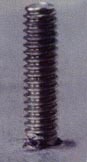
Highest power density output, with High-purity fused, translucent quartz face.
Face Options
Opaque quartz is the standard face on the Q-Series panel heaters. The properties of quartz make it a very efficient radiator of infrared energy. Both our expertise with infrared heaters and ability to fuse quartz enable us to be the only company in the world to manufacture this unique heater. The back of each fused quartz face is precision machined to hold the resistance coil. With the coils resting in the grooves, the coils are surrounded by three walls of quartz, effectively maximizing the energy output of the heater. A reflective insulating fiber board is added behind the heating element to direct the infrared energy forward through the quartz face. Double layer insulation is installed behind the insulating board to decrease back heat loss. Aluminized steel casings and welded stainless steel terminations are standard throughout the heater.
The orientation of the Q-Series heater must be controlled, and its heating elements are not cemented in place. Therefore, it is important to assure that the heating elements are not placed in a vertical orientation. That would eventually result in a slumping of the coils and a greatly reduced life expectancy.
Q-Series Specifications
The Q-Series heaters can be constructed up to 12″ (305 mm) wide and 12″ (305 mm) in length. The QH model has a maximum watt density of 60 watts/in2 (93 kW/m2). The Q-Series heaters have a durability defined by a typical life expectancy of 25,000 hours and a high radiant efficiency of 82%. Because the heater design does not depend on an external reflector, the heaters maintain a consistently high radiant efficiency over time. The Q-Series heat transfer rate for 60/in2 (93 kW/m2) is 6.04 btu/sq. ft./sec. delivered to the heating element.
Our QH model uses a very high purity 99.998% quartz. The QH model is often used for semiconductor applications because of the quartz’s high purity percentage, temperature uniformity and ability to create unique shapes. The Q-Series heater is additionally used in several applications requiring high-intensity heat, such as high-speed drying and curing lines.


Q-Series Panel Heater Models: QH
Our Q-Series infrared panel heaters offer the highest power density output available in an infrared panel heater. High-purity fused, translucent quartz is used for the heater’s face.
Features:
- Grooved, fused, translucent quartz emitter surface plate (QH)
- Precision-wound resistance wire
- Heavy gauge aluminized steel frame
- High-temperature, rigid refractory
- Support angle to secure the quart plate in the frame
- Refractory blanket insulation layer
- Bulk insulation to minimize back heat loss
- Ceramic bushings to insulate terminals
- Stainless steel terminals welded for long life
- Quartz thermowell tube (optional)

Q-Series Warm-up Curve
The warm-up curves are measured from heaters running facedown in open air. The thermocouple is located in a standard location inside a thermowell behind the coil. The curves will change depending on the environment and thermocouple location.

- Construction Options
- Voltage, Phase, and Other Options
- Mounting Options
- Temperature Sensing Options
- Electrical Termination Options
Housing
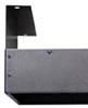
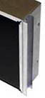
The heater’s case or housing can be manufactured using aluminized steel or stainless steel. Additionally, in some cases the heater can be supplied without a case.
Aluminized steel is the most commonly used case material. It can achieve very high temperatures — namely 1200°F (649°C) — without flaking, discoloring or degrading; this assures that the heater’s case will outlive the heater itself. The housing is typically riveted together. The rivets, along with slots in the heater case, permit controlled expansion and contraction during heat-up and cool-down processes. Some applications require the slots to be removed, which can be achieved for many engineering designs.
Stainless steel’s advantages of enhanced cleanliness and a very polished appearance make it a good choice for food and semiconductor applications. Because the 304 grade of stainless steel will discolor at a lower temperature than aluminized steel, the 310 grade of stainless steel is often chosen for extremely high temperature applications. A stainless steel case is usually riveted together in the same manner as aluminized steel though there are some applications where the stainless case is welded and polished for superior cleanliness and cosmetic appeal. Additionally, those housings are usually supplied without expansion slots. This construction is typically implemented in our glass, koramic and quartz face heaters.
The last option, called board only, is to have no case at all for the heater. This heater is usually an F-Series model without the housing, insulation or pre-constructed panel design. Customers who have in-house sheet metal capability will sometimes choose to buy the heating element, fiber board, quartz fabric and cement as a completed assembly. The remaining components of the panel fall under the customer’s responsibility. This approach shifts much of the heater’s construction and warranty issues toward the customer.
Standard Dimensions
| Width (mm) |
Length (mm) |
F | FBA | G | K | M | Q | ||||
| 6″ (152.4) |
12″ (304.8) |
18″ (457.2) |
24″ (609.6) |
30″ (762) |
36″ (914.4) |
X | X | X | X | X | |
| 6″ (152.4) |
42″ (1066.8) |
48″ (1219.2) |
54″ (1371.6) |
60″ (1524) |
X | X | X | X | |||
| 10″ (254) |
4″ (101.6) |
6″ (152.4) |
8″ (203.2) |
10″ (254) |
X | ||||||
| 12″ (304.8) |
6″ (152.4) |
10″ (254) |
12″ (304.8) |
X | |||||||
| 12″ (304.8) |
12″ (304.8) |
18″ (457.2) |
24″ (609.6) |
30″ (762) |
36″ (914.4) |
X | X | X | X | X | |
| 12″ (304.8) |
42″ (1066.8) |
48″ (1219.2) |
54″ (1371.6) |
60″ (1524) |
X | X | X | 42″ or 48″ |
|||
| 12″ (304.8) |
72″ (1828.8) |
84″ (2133.6) |
X | 72″ only |
|||||||
| 16″ (406.4) |
16″ (406.4) |
24″ (609.6) |
X | X | X | X | X | ||||
| 18″ (457.2) |
18″ (457.2) |
X | X | X | X | X | |||||
| 24″ (609.6) |
24″ (609.6) |
X | X | ||||||||
Note: Solar Products specializes in manufacturing custom heaters that match a specific application. Listed above are standard heater dimensions.
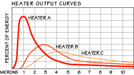 The wavelength output from our heaters ranges from 2.3 microns to 6 microns and is inversely proportional to heater temperature; that is to say, as the temperature increases the wavelength decreases. All heaters output energy over a range of wavelengths as depicted in the heater output curves appearing below. Heater ‘A’ displays a typical shortwave heater, Heater ‘B’ displays a typical medium-wave heater, and Heater ‘C’ displays a typical long-wave heater. All of the curves have one common characteristic. If a line were drawn vertically through the peak of the curve, then the area left of the line represents 25% of the total energy output shorter than the peak wavelength, and the area to the right of the curve represents 75% of the energy at a longer wavelength than the peak.
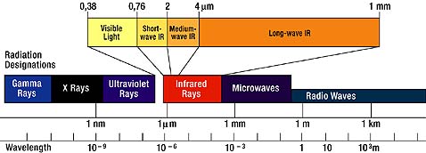


 An end mount thermowell is the most common design. The thermowell is either a quartz tube (most common because of faster response) or ceramic tube located parallel to the heating element. The tube is typically 5″ (127mm) long and has an inner diameter of 0.157″ (4 mm). A thermocouple bracket is mounted outside the thermowell tube in order to assist in proper positioning and holding the thermocouple in place. The thermocouple is then located 4″ into the thermowell and fastened using the bracket. It is important to assure that the thermocouple is not over extended into the thermowell, which may result in incorrect temperature readings or heater failure. A thermocouple with a male plug is displayed.
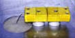 The back mount design makes use of an L-shaped quartz tube that runs perpendicular to the coil toward the back of the heater. The thermowell then makes an arced 90° bend, continuing for a short distance parallel to the heating element. This design is used when the heaters are surrounded, not allowing side access, and requires the use of a .040″ (1 mm) diameter thermocouple in order to make the 90° bend. A thermocouple with a male/female plug combination is displayed. This design is not available for the Q-Series.
 The bayonet style thermowell is sometimes used with metal, koramic, glass, and quartz face heaters to measure the actual face temperature (emitting surface) as opposed to the heating element temperature. The thermocouple goes through a bayonet fitting and is compressed using a stainless steel spring. This approach assures that the tip of the thermocouple makes correct contact with the heater face.
 It is becoming more common for equipment manufacturers and end users to make use of optical pyrometers, or non-contact thermometers, to sense product temperature as opposed to heater temperature. In virtually all applications, product temperature is the temperature of choice. Heater temperature is only used as a reference in order to attain a particular product temperature. The reduced price for these devices and the quest for better process control has driven the use of optical pyrometers. For that reason, it is sometimes necessary to provide an opening (1.5″ – 2″ (38 – 51 mm) diameter hole) through the heater where the optical pyrometer can be placed to monitor the product temperature. The pyrometer hole size can vary based on the specific requirements. A smaller hole is always preferred in order to avoid nonuniform heating of the product.
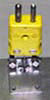
 The flag type terminal consists of a flat piece of stainless steel that is .350″ (8.9mm) wide x .032″ (0.81mm) thick with a .187″ (4.75mm) hole near the end. This is our preferred termination because of the excellent electrical contact that is achieved with this type of connection. All of the electrical terminal options are typically housed within a 2″ x 4″ (51mm x 101.6 mm) or 4″ x 4″ (101.6 mm x 101.6 mm) electrical box.
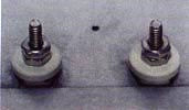 The stud type terminal consists of a threaded stud that exits the heater for an electrical connection. A number of different connection lengths and stud sizes are available. The disadvantage of a stud type terminal is the electrical current limit of the stud. An electrical current is only carried on the threads of the stud.
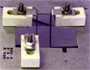 Another version of this connection is the ceramic block flag type terminal. This design makes use of a flag type terminal exiting the heater that is bent over a ceramic mounting block with a vertically mounted stud. This approach uses the stud as a means of easy connection but not as a current-carrying device. Therefore, higher current can be carried through the electrical connection. This type of connection is not available on all heaters.
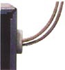 Wire leads is a fourth termination option available on Solar Products’ heaters. This option is only available on heaters having a watt density lower than 10 watts per square inch (15.5 kW/m2). A high temperature wire is resistance welded to an intermediate piece of stainless steel, and the steel piece is in turn resistance welded to the heating element. The wire leads can be fabricated in any required length.